
A free-flight glider (A1) for beginners
Dr. Mencel, CSSR (coach of the Czech National Free Flight Team), kindly provided me with the “KIKI” model for publication. In addition to being a fun model to build, it has proven particularly effective for beginners in high-launch flying. The model has often been successful in A1 competitions.
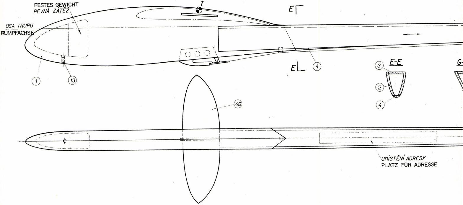
We carve the fuselage nose from two limba wood strips (No. 1). Special care must be taken when cutting the slot for the tab; be sure to maintain a right angle and the correct angle of attack exactly. Next, secure approximately 50 g of rolled lead in the lead chamber. Now we can glue the two fuselage halves together using white glue. Next, fit the two cut-to-size fuselage stringers (No. 2). At the same time, we attach the upper stringer (No. 3). This should rest against the workbench when the fuselage is assembled. To glue on the stringer (No. 4), the two side stringers are sanded flat. The end strip (No. 5) is trimmed to fit and glued in place. We cut the shape of the launch hook (No. 6) from 2 mm aluminum sheet. A 1 mm hole is drilled at the bottom for (Part 22), the curve release mechanism. We clamp a 1 mm x 5 mm steel wire into this hole. We bend three eyelets (No. 7) from 0.2 mm tinplate. To do this, we proceed as follows: cut a rectangular piece of tinplate measuring 4 x 10 mm. Place a 1 mm steel wire in the center of the narrow side and bend the sheet metal around it by hand. Use pliers to make the curve even more pronounced. Pull out the steel wire, and the eyelet is ready.
We make parts 8, 9, and 10 from 2 mm pine round stock. The stop (No. 11) and the height control support (No. 12) are made from 1.5 mm thick plywood and glued in place. The M4 x 6 threaded bolt (No. 13) can be purchased from a specialty retailer. The side control is glued together from parts 14, 15, and 16. Note the grain direction of the wood as shown on the plan!
No. 16 is a plywood reinforcement.
To complete the fuselage, attach the rudder with its mechanism. No. 17: two pieces made of 2 mm plywood. No. 18 is made of 2 mm aluminum, measuring 2 x 4 x 15 mm, with two M2 threaded holes for the threaded bolts (No. 19) and the brass locknuts (No. 51). A Perlon thread, approx. 0.3, connects the rudder to the spring plate (No. 22). If you are unable to fabricate the mechanical parts yourself, you can obtain them from the author. A rubber band (No. 21) is tied between the Perlon thread (No. 20). The rudder can now be attached either to the left or to the right using the rubber stop (No. 52).
We cut a sample rib (No. 23) from 1.5 mm plywood. This serves as our template. Cut twelve 1 mm balsa ribs and, for the center section, two 2 mm ribs. If you guide the knife perfectly vertically, every rib will be identical. After cutting the end strip (No. 24) with rib notches, the main spar (No. 25), and the nose strip (No. 26), assembly can be carried out directly on the plan using pins. For glue, we use a synthetic resin such as Britt-Fix, Uhu-hart, etc. To attach the skin, the nose spar must be sanded flush with the ribs according to the plan. A filler block (28) is fitted in the center of the elevator; this serves to accommodate the elevator mounts (No. 31: 2 mm round pine wood, tapered, and 1 mm steel wire thermal stop pin). To reinforce the nose spar at the stop, we glue a 4x15 mm strip of tinplate in place according to the plan. After attaching the edge strips (29), the entire frame is smoothly sanded with fine-grit sandpaper.
Model builders should pay special attention to the wing, as future flight performance depends largely on it. The construction is similar to that of the elevator. To assemble the left half of the wing, rub the pattern with an oil-soaked cloth—but not one that is too wet. This makes the pattern translucent. It also has the advantage that areas where glue has been applied to the pattern will not stick.
Once again, we fabricate a template rib from 1.5 mm thick plywood (35). This will also serve as one of the six center ribs to accommodate the aluminum tab (49). The end ribs (No. 33) are made of 1 mm plywood; all other ribs are made of 2 mm balsa (medium-hard). The main spars (42, 43, 44) are made of hard balsa. The nose spars (46) and trailing edge are made of medium-hard balsa. First, the ribs are temporarily attached to the main spar (42). A 1.5 mm shim is clamped under the leading edge of the trailing edge—this ensures the wing maintains its correct profile. At the wing bend, the ribs are glued at an angle using a homemade template and sanded flat on the end faces. After attaching the skin (47) and the leading-edge curves (50), the entire frame is also carefully and neatly sanded down.
The entire airframe is painted with a 1:1 mixture of primer and thinner and then lightly sanded again. The model will look its best if you cover it with fabric according to the color code on the plan. For inexperienced model builders, I recommend applying the covering using Glutofix. Use thin Japanese paper! Start with the underside. Coat all wooden parts where the paper will be applied with Glutofix, then stretch the covering on without any wrinkles. After it dries, spray it with water.
Apply the first coat of varnish using a 1:1 mixture of varnish and thinner. After air-drying, clamp the model—not too early—to prevent warping. Apply a second coat with a mixture of 2/3 Spannlack and 1/3 thinner. If necessary, apply a third coat with the same mixture. Let it dry for two days.
After assembling the model, adjust the center of gravity using small lead balls.
When learning to fly, beginners are best off bringing along an experienced colleague. This will save them a lot of time and prevent unnecessary damage.
If you want to try it on your own, proceed as follows: Hold the model by the fuselage behind the center of gravity with your arm outstretched on level ground, tilted slightly downward, and push it into the air against the wind. If the model plunges sharply downward, some lead must be removed. If the model performs a so-called “choppy flight,” more lead must be added until, when launched from the hand, it flies a distance of approximately 20 meters. I hope you have fun building and flying. W. Heise
P.S. 1:1 scale plans available from the editor.
Wingspan | 1,350 mm |
Fuselage length | 745 mm |
Total wing area | 18.96 dm² |
Wing area | 15.90 dm² |
Elevator area | 3.06 dm² |
Weight | 236 g |
Designer | Jiří Novotný |


News from HEBU

EURO CONTEST GLIDER ACRO TOUR AUSTRIA 2026

TEAM MANAGER "THIS" BOSSHARD
 Rodito Nussbaumer

YOU KNOW WHAT I MEAN? 125 YEARS OF THE SWISS AERO CLUB
 Emil Giezendanner

F3A EUROPEAN CHAMPIONSHIPS IN ST-MACAIRE, FRANCE
 Matthias Bosshard

HORIZON HOBBY/LEMACO NEWS: MICRO OV-10 BRONCO 645 MM BY E-FLITE

PRIDE AND GOOD IDEAS
 Markus Nussbaumer

BY YOUTH, FOR YOUTH
Lorena Betschen
34th HAHNENMOOS ALPINE MODEL AIRPLANE CAMP
Res Dauwalder
TRY-OUT DAY AT MFV WETTINGEN
Urs Keller
52. 2026 ALPS CUP
Emil Giezendanner
TWIN TOWN PARTNERSHIP
Wolfgang Voeller
ATOM, THE NEW DOUBLE-DECKER FROM CPLR
Matthias Bosshard
CORSAIR F4U – A WARBIRD WITH A MEMORABLE LOOK
Jürgen Rosenberger, Jürgen Prinz
SUMMER FUN 2026 AT MG USTER
Martin Wunderli
What's New at Leomotion.com

THE PC-21 STORY
Emil Giezendanner
COUPE DES ALPES – OBSERVE AND LEARN
Rodito Nussbaumer
SMALL, MODEL-LIKE SAILBOATS
Res Dauwalder
WELCOME, NEW MEMBER!
Andrea Bolliger
FREE FLIGHT IN THE MIDDLE OF SUMMER
Urs Muntwyler
INSIGHTS INTO THE HISTORY OF SEAPLANES

NEWS FROM HEBU
 Julia Bucher

FROM 0 TO 100
Markus Nussbaumer
MEMORIES
Wolfgang Völler
NOS REGION – A HUB FOR ELECTRIC AVIATION
Emil Giezendanner
DO YOU KNOW WHAT I MEAN IN THE LAND OF SMILES?
Emil Giezendanner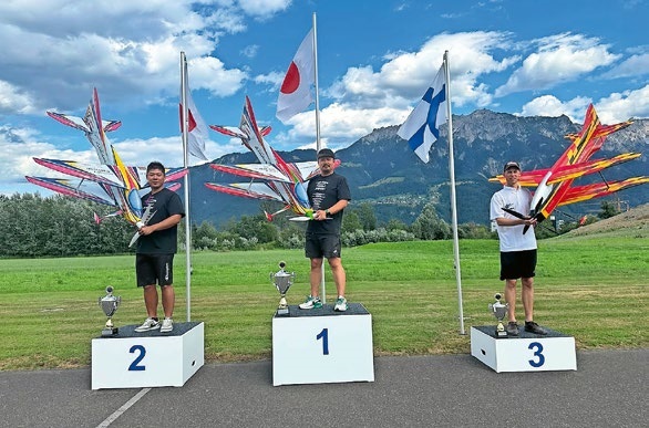
A SPECTACULAR F3A WORLD CUP IN THE PRINCIPALITY OF LIECHTENSTEIN
Emil Giezendanner