
DIY: Lockheed Martin F-35 Lightning II
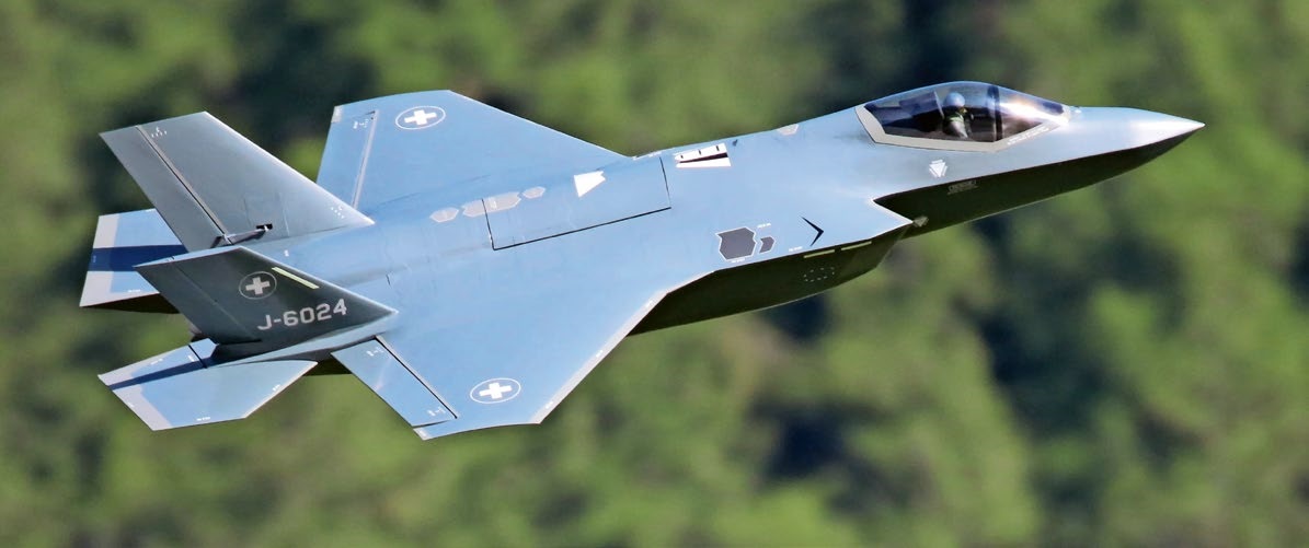
After Swiss voters rejected the purchase of the Saab Gripen E fighter jet in a referendum in May 2014, a vote was held in 2020 on a loan to acquire a new aircraft for the Air Force. As is well known, the vote this time passed by a razor-thin margin. The loan was approved, though the choice of aircraft model was left out of the vote and delegated to the Federal Council. The Federal Council then decided, on the recommendation of a panel of experts, to select the Lockheed Martin F-35A Lightning II.
Since we’ve been deeply involved in electric jet aviation for more than 25 years and have already designed and built various models ourselves, it was clear that we wanted to take on the challenge of replicating the F-35A. We began brainstorming in the summer of 2022. Since we still had an unused Schübeler DS-77-HST impeller with a 120 mm diameter that we wanted to use, our vision was as follows: The model should be approximately 175 cm long with a corresponding wingspan and, based on the impeller’s thrust, weigh between 6 and 7 kg. The search for a model
Daniel took over the online research, though the usable results were disappointing. A ready-made model was out of the question. He stumbled upon a small ray of hope by chance on a CAD data platform, where a South Korean model builder had published the wood-milling files for a small F-35A. The proportions seemed to fit well, but at 145 cm in length, the model was too small for what we had in mind. A fellow modeler we knew left a message in the guestbook of the platform in question, thanking the creator for the excellent milling files. We had found the proverbial “needle in a haystack,” and this led to the story of how the project came to be.
We quickly made initial contact with Martin Weibel, the model-building colleague mentioned above. According to him, he was already building a small F-35A based on the CNC files from South Korea. With the consent of the South Korean model-building colleague, he even plans to offer a set of milled parts. Martin was immediately enthusiastic about our idea to build a larger version. He was willing to adapt the existing file so that a set of frames for the fuselage, wings, horizontal stabilizer, and vertical stabilizer could be milled to the size we desired. For simplicity’s sake, all dimensions were multiplied by a factor of 1.25. This resulted in a length of 182 cm and a wingspan of 125 cm—exactly the scale we had envisioned. We gave Martin the go-ahead, and so the F-35 adventure could begin. We also agreed that we would keep him regularly
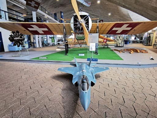
We would keep him informed about our construction progress, thereby providing him with valuable insights. In fact, he had already become enthusiastic about the larger project himself and decided to offer a milling part set in this size as well. It was foreseeable that this change in plans would take some time. We were thrilled when we received the news that the first fuselage frames were ready, so we immediately scheduled a pickup time. Perfect milled parts and a detailed discussion with Martin more than made up for the long trip to the beautiful Gürbetal valley. He was to mail us the remaining milled parts for the tail assembly and the wing as soon as they were ready.
Milled parts tempt you to get started as quickly as possible to see the first results. This may be true for an off-the-shelf model, but not for a prototype. Every step had to be carefully considered. The following parameters must be coordinated before construction begins: the positions of the impeller and battery to ensure the center of gravity is correct, as well as their accessibility; the installation of the electronics; the installation of the landing gear; and so on. Together, we
We spent a lot of time discussing these questions and finding solutions. The fuselage consists of three separate segments. 1. Rear fuselage section: Tail section with mounts for the horizontal and vertical stabilizers, as well as mounts for the propeller, main landing gear, and wings; 2. Middle fuselage section: segment containing the air ducts. 3. Forward fuselage section: front segment with battery tray, nose landing gear mount, and cockpit. All parts were first assembled (without adhesive) to test various positioning options. If there was room for improvement, we asked Martin to mill new parts for us. Once we had found a solution for everything, we proceeded to glue all the parts together. For this, we did not use superglue, but rather the PUR wood adhesive Mirapur 9515 Rapid. The Y-tube was 3D-printed by Martin and was designed as a closed duct. Since we are firm advocates of the open-duct system, we implemented that here as well. The air inlets were shortened so that the Y-tube ends 10 cm in front of the impeller. From the very beginning, the impeller position dictated by the smaller model was a thorn in our side, as it made it nearly impossible to
achieve. We therefore decided to move the impeller back approximately 15 cm, which was easily possible. However, some uncertainty remained, as we did not yet know how the weight of the thrust tube and tail surfaces would affect the design. We fabricated the thrust tube ourselves using the familiar method: Using a heating wire, we cut a tube from Styrofoam to the required length and with the appropriate inlet and outlet diameters, and wrapped it with adhesive film. We then coated it with release wax and a release agent. After allowing it to dry for a while, we laminated two layers of fiberglass fabric (49 g linen and 100 g twill weave) over it, along with spot reinforcements using carbon rovings. After the usual curing time, we dissolved the Styrofoam with a little nitro thinner. A perfectly fitting, lightweight thrust tube was born. Special attention also had to be paid to the interplay between the landing gear position, leg length, and wheel size. Under no circumstances was the model allowed to have a negative angle of attack at ground level. We set this to +2°, which later proved to be perfect.
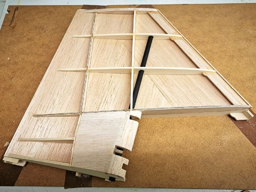
The two vertical stabilizers were assembled on two jigs that Martin had provided us. They are mounted to the fuselage using two carbon tubes. The rudder flaps are mounted in grooves and are controlled by a servo mounted on the inside of each stabilizer. We did not glue the vertical stabilizers to the fuselage, but simply secured them against slipping out using adhesive tape. Since these are fully symmetrical stabilizers, they can also
be swapped. The two pendulum elevators are constructed in much the same way as the vertical stabilizers. A bigger challenge, however, was their mounting and attachment to the fuselage. The original plan was to connect them permanently to the fuselage. For transport reasons, we discussed with Martin the possibility of making them removable. Martin then came up with the idea of using screw connections to achieve this. To be on the safe side, we added additional reinforcements to the rear section of the fuselage using carbon and aramid fabric.
The two wings are also assembled on separate frames. These are fully planked spar wings, though Martin has made certain modifications to them. The aileron flaps are also mounted in recesses. One special feature, however, is worth mentioning here. The entire wing has a slight camber, just like the original. This means that while the hinge axis runs straight, the wing curves slightly around it. This is possible because only small aileron deflections are required.
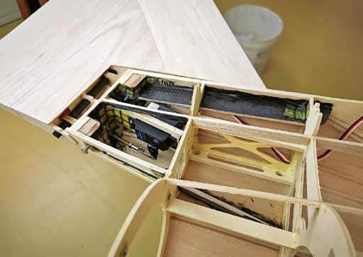
There was also plenty to discuss when it came to installing the electronics. We considered various options until we found the optimal locations for the receiver, the landing gear control, and the dual power supply. A small cardboard-and-wood panel above the impeller, directly under the fuselage cover, proved to be the ideal spot. Once the electronics were installed, we moved on to covering the fuselage with 2-mm balsa wood.
| Scale: | 1:8.5 |
| Wingspan: | 124 cm |
| Length: | 182 cm |
| Weight: | 6.73 kg |
| Drive: | Schübeler DS – 77 DIA HST/ø 120 mm |
| Cells: | 12S 5000 mAh (Leomotion/Fullymax) |
| Retractable landing gear: | Elektron ER 30 evo |
| Landing gear struts: | Nose: Elektron Main: Jet – 1A |
| Servos: | All Futaba HV |
| Receiver: | Futaba R7014 SB |
| Battery switch: | Powerbox Sensor V3 |
| Telemetry: | SM Modellbau UniSens-E |
The first taxiing tests were conducted at the Emmen military airfield. This airfield will play a key role in the rollout of the original aircraft.
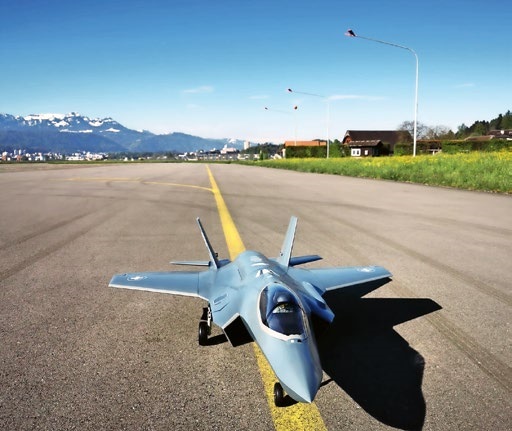
Finally, we had all the components together so we could take an initial weight measurement and get an idea of the center of gravity. Everything was assembled provisionally for the first time. We breathed a sigh of relief when the digital scale read just under 6 kg. Great—first test passed. Things got exciting when it came to the center of gravity. Initial shock: tail-heavy! Had moving the impeller backward been the wrong decision after all? We moved the two 6S 5,000 mAh battery packs further forward from their intended position on the battery board. Just before we could move them any further forward due to space constraints, the center of gravity was right. Since larger battery packs with more capacity (longer flight time) would be heavier and therefore need to be placed farther back, our plan had worked out perfectly.
To save time and effort, we decided against applying a fiberglass-reinforced plastic (FRP) coating to the airframe and opted instead for Orastick film. However, this means that we must work with extreme care when covering the model, as even the slightest unevenness will inevitably be visible under the film. Oracover also offers films in a matte finish. We chose the “Seafire Sea Gray” color, as it closely matches the original color. We imitated the surface textures of the original visible in certain areas using a thicker adhesive film, which was applied before covering the surface with the main film. The registration numbers and national insignia were produced using a cutting plotter. Smaller lettering and decals were supplied by Tailor Made Decals and were applied only after the maiden flight.
In February 2024, the model was finished and ready for its maiden flight. But then the long wait began. Poor spring weather repeatedly prevented the maiden flight from taking place. On June 16, the moment finally arrived. Everything went according to plan. A few select people set up their cameras and video cameras. Daniel concentrated, applied thrust, and pulled enthusiastically on the elevator. The F-35A took off and flew very promisingly right from the start. A perfect landing relieved the tension among everyone involved, giving way to great enthusiasm. During subsequent flights, fine adjustments were made to the control surface deflections, and the center of gravity was slightly adjusted.
More photos and a video of the maiden flight can be found on our website at www.ejets-eichenberger.ch. Anyone interested in
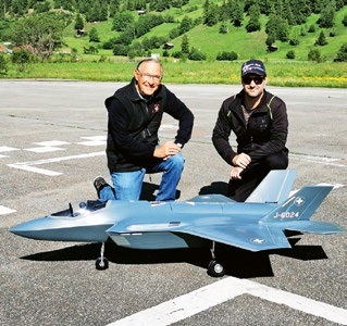
Those interested in milled parts can contact Martin Weibel at www.modellbau-weibel.ch. The excellent fit makes building these models a real pleasure. Some experience with model building and flying is certainly an advantage.


News from HEBU

EURO CONTEST GLIDER ACRO TOUR AUSTRIA 2026

TEAM MANAGER "THIS" BOSSHARD
 Rodito Nussbaumer

YOU KNOW WHAT I MEAN? 125 YEARS OF THE SWISS AERO CLUB
 Emil Giezendanner

F3A EUROPEAN CHAMPIONSHIPS IN ST-MACAIRE, FRANCE
 Matthias Bosshard

HORIZON HOBBY/LEMACO NEWS: MICRO OV-10 BRONCO 645 MM BY E-FLITE

PRIDE AND GOOD IDEAS
 Markus Nussbaumer

34th HAHNENMOOS ALPINE MODEL AIRPLANE CAMP
Res Dauwalder
TRY-OUT DAY AT MFV WETTINGEN
Urs Keller
52. 2026 ALPS CUP
Emil Giezendanner
BY YOUTH, FOR YOUTH
Lorena Betschen
ATOM, THE NEW DOUBLE-DECKER FROM CPLR
Matthias Bosshard
CORSAIR F4U – A WARBIRD WITH A MEMORABLE LOOK
Jürgen Rosenberger, Jürgen Prinz
SUMMER FUN 2026 AT MG USTER
Martin Wunderli
What's New at Leomotion.com

THE PC-21 STORY
Emil Giezendanner
COUPE DES ALPES – OBSERVE AND LEARN
Rodito Nussbaumer
TWIN TOWN PARTNERSHIP
Wolfgang Voeller
SMALL, MODEL-LIKE SAILBOATS
Res Dauwalder
WELCOME, NEW MEMBER!
Andrea Bolliger
FREE FLIGHT IN THE MIDDLE OF SUMMER
Urs Muntwyler
INSIGHTS INTO THE HISTORY OF SEAPLANES

NEWS FROM HEBU
 Julia Bucher

FROM 0 TO 100
Markus Nussbaumer
MEMORIES
Wolfgang Völler
NOS REGION – A HUB FOR ELECTRIC AVIATION
Emil Giezendanner
DO YOU KNOW WHAT I MEAN IN THE LAND OF SMILES?
Emil Giezendanner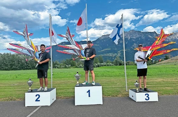
A SPECTACULAR F3A WORLD CUP IN THE PRINCIPALITY OF LIECHTENSTEIN
Emil Giezendanner