
Lighting and Signaling on Model Airplanes Using Modern Power LEDs – Part 2: Practical Applications
"Light Up Your Aircraft"
—A concrete project that serves as a testing ground for your own ideas and concepts
Now that we’ve covered the basics in the first part of our exploration of the world of lighting and optical signaling in model aircraft, we’ll move on to applying this knowledge to our own project. The reason we’re using the term “project” here—perhaps a bit of an exaggeration—stems from our practical experience that even simple LED lighting systems require us to make certain assessments, assumptions, and decisions in order to be successfully implemented. This primarily concerns the selection of components (MFS Issue 5/2009) and the proper sizing of the lighting system’s power supply. To this end, we’ve devised a simple “reference design”—integrated into an electric model airplane—that can be built quickly and with great enjoyment, while also effectively demonstrating lighting on the model airplane.
Furthermore, we use the equipped model as a platform for an impressive experiment to objectively demonstrate the effectiveness of the lighting solution, since we maintain that this is about more than just having fun with model building. With a truly well-chosen lighting system, new and useful features are created that can greatly enrich our hobby—a new playground for hobbyists, tinkerers, and creative minds.
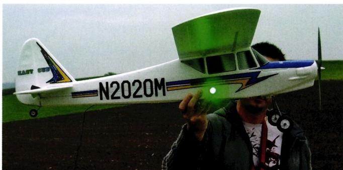
Our mission is to demonstrate the capabilities of high-performance LED lighting. That’s why we’ve chosen a simple electric trainer—in our case, the Multiplex Easy Cup, which is constructed from EPP (Figure 1). We’ll omit design details as much as possible. Likewise, realism isn’t a priority at this point—rather, ease of use and performance in operation are what matter. This model provides us with an ideal platform.
We have decided on the following features: red and green navigation lights, a white strobe light, and a taxi light—all of which can be turned on and off.
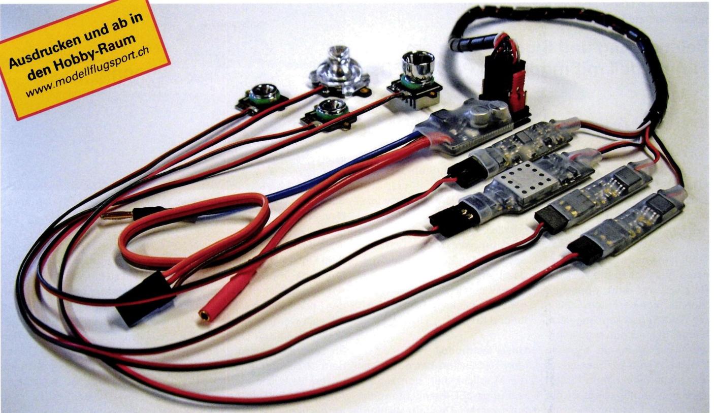
The following system components from www.innoflyer.ch will be used; they are expected to be available on the market toward the end of 2009 (Figure 2): Power Panel with optocoupler for separate power supply from a 2-cell LiPo battery (a capacity of approx. 1 Ah is sufficient for our tests) and connection capability for up to 5 loads. Nav Lights with a low-cost analog driver, red and green, 13-degree wide-mode optics. Taxi light headlight with 7-degree spot-mode optics, full-power AMP (Automatic Maximum Power and Temperature Control) with an RC interface.
Installing the system components is virtually the same as installing the components of a remote control system. Careful routing of the electrical cables prevents incorrect connections and mechanical damage to the insulation during operation. As is generally the case, care must be taken to ensure that the receiver antenna maintains a minimum distance of about 2 cm from components and cables along its entire length.
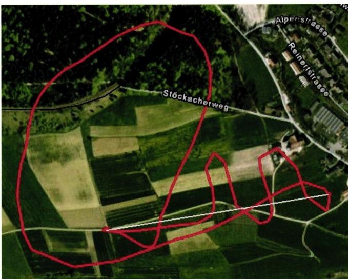
Without further ado, we equipped our model with a payload—a Garmin Etrex Vista HCx—so we could use
Google Earth to gather reliable data on each test flight (Figure 3).
During the test flight, it became clear that the colors green and red are much more easily visible at long distances than the white strobe light. The strobe light is clearly visible up to a distance of about 150 m. Beyond that, you really have to concentrate. The situation was quite different with the constantly glowing, colored navigation lights. These were clearly and unmistakably visible up to a distance of 500 m without any problems. Flying any further with our test model was out of the question, as practically only the light spot was still clearly visible.
To get a better idea of the test environment and the test itself, please refer to the corresponding images in this article. “Track1” and “Track2” (Figure 4) show a bird’s-eye view of the flight path. The maximum distances are marked on each. These are approximately 500 m. Unfortunately, due to the resolution of the digital images and the distance of the model, it was not possible to obtain meaningful images of the light intensity. Incidentally, it’s truly amazing to realize what our eyes are capable of resolving.
The reduced visibility of the strobe light may come as a surprise at first, but it can be explained as follows: The light output—
The performance of both light source types is roughly the same. A major difference lies in the optics used in each. The strobe light uses a 360° optical system, which provides a wide field of view. However, the energy emitted per unit area is lower. The navigation lights use an optical system with a narrower beam
angle. This results in a slightly smaller field of view, but the luminous intensity within that field is significantly higher. The color of the LEDs was another factor that clearly improved visibility compared to white light. It is entirely possible that a red strobe light with a different optical system could
achieve results just as good as those with the Nav Lights we used. In any case, we were surprised at how much the aircraft’s visibility improved. In an application like this, the lighting isn’t just “pretty”—it provides clear technical added value. We hope
have convinced you of this added value with this test flight. We hope this inspires you to try out lighting on your own model aircraft. For more information on the topic “Light Up Your Aircraft,” visit www.innoflyer.ch.


News from HEBU

EURO CONTEST GLIDER ACRO TOUR AUSTRIA 2026

TEAM MANAGER "THIS" BOSSHARD
 Rodito Nussbaumer

YOU KNOW WHAT I MEAN? 125 YEARS OF THE SWISS AERO CLUB
 Emil Giezendanner

F3A EUROPEAN CHAMPIONSHIPS IN ST-MACAIRE, FRANCE
 Matthias Bosshard

HORIZON HOBBY/LEMACO NEWS: MICRO OV-10 BRONCO 645 MM BY E-FLITE

PRIDE AND GOOD IDEAS
 Markus Nussbaumer

34th HAHNENMOOS ALPINE MODEL AIRPLANE CAMP
Res Dauwalder
TRY-OUT DAY AT MFV WETTINGEN
Urs Keller
52. 2026 ALPS CUP
Emil Giezendanner
BY YOUTH, FOR YOUTH
Lorena Betschen
ATOM, THE NEW DOUBLE-DECKER FROM CPLR
Matthias Bosshard
CORSAIR F4U – A WARBIRD WITH A MEMORABLE LOOK
Jürgen Rosenberger, Jürgen Prinz
SUMMER FUN 2026 AT MG USTER
Martin Wunderli
What's New at Leomotion.com

THE PC-21 STORY
Emil Giezendanner
COUPE DES ALPES – OBSERVE AND LEARN
Rodito Nussbaumer
TWIN TOWN PARTNERSHIP
Wolfgang Voeller
SMALL, MODEL-LIKE SAILBOATS
Res Dauwalder
WELCOME, NEW MEMBER!
Andrea Bolliger
FREE FLIGHT IN THE MIDDLE OF SUMMER
Urs Muntwyler
INSIGHTS INTO THE HISTORY OF SEAPLANES

NEWS FROM HEBU
 Julia Bucher

FROM 0 TO 100
Markus Nussbaumer
MEMORIES
Wolfgang Völler
NOS REGION – A HUB FOR ELECTRIC AVIATION
Emil Giezendanner
DO YOU KNOW WHAT I MEAN IN THE LAND OF SMILES?
Emil Giezendanner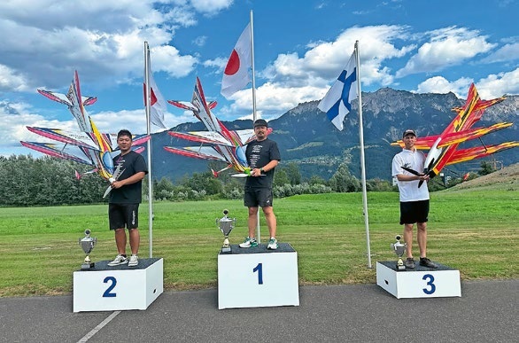
A SPECTACULAR F3A WORLD CUP IN THE PRINCIPALITY OF LIECHTENSTEIN
Emil Giezendanner